Home > CAD Parts > Brushed DC Motor
- Materials and Equipment
- Print the Parts
- Assemble the Windings
- Wind the Electromagnetic Coils
- Build the Commutator
- Build the Power Circuit
- Install the Stator Magnets
- Test and Fix
- Designs, Videos, and STL Files
- Other Fun Stuff: Web-Browser Control with a Digital Tachometer Circuit
- Things to Improve
- References
Materials and Equipment
Required:
- Copper sheet: Used to build commutator plates.
- 30 AWG enameled magnet wire: Used to create electromagnetic windings.
- Soft iron rod: Enhances the field strength of electromagnetic windings.
- Hacksaw: Or some other way to cut lengths of the soft iron rod.
- Ceramic magnets: Form the fixed stator fields of the motor.
- Bearings: Holds the rotor.
- Carbon motor brushes: Conducts current from a source to the commutator by physical contact.
- Superglue: Used in a couple spots to hold parts together (e.g., commutator plates to the rotor).
- Thin-gauge wire (e.g., 22 AWG jumper cables as provided in kits like this): For providing current to the carbon motor brushes.
- Soldering iron: Wire connections.
- Solder: Wire connections.
- DC power supply: This is usable depending on the total resistance of the windings. If the resistance is too low because the windings are too small, then this power supply will short and self-disable. However, this supply works fine in all builds of the motors described on this page. If you go with this power supply, then also get a DC power jack to connect the supply to the carbon motor brushes. It should be possible to wire several batteries together for power, but I do not provide instructions for this. I can only say that a single 9-volt battery is insufficient. I tried it, and it was not strong enough.
- Lots of patience: It takes several hours to print the plastic parts and then several more hours to build and assemble, assuming you get it right the first time, which is not assured!
Optional but useful:
- Electrical tape: To wrap the coils.
- Soldering station: The connections, particularly to the commutator, are difficult to solder without this handy tool.
- Shrink tubing: For soldered connections.
- Autoranging multimeter: Very helpful when checking winding resistance and circuit integrity.
- Alligator clips: Useful when checking circuits and changing wiring.
- Files: Removing extraneous plastic when assembling parts.
- Vise: Useful when cutting segments of the iron rod and winding the electromagnetic coils.
- Circuit breadboard: Useful when building circuitry around the motor such as on/off switches and relays, LED indicators, and tachometers.
Print the Parts
See here for the 3d-printing tech that I use. Links to part files for particular designs can be found at the bottom of this page. A few printing tips:
- It’s possible to lay out all parts for a single print, as long as your printer’s build volume is sufficiently large.
-
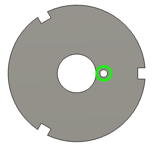
The winding holder prints best when it is lying flat with the central rotor hole vertical. To assist with this, I have added a small planar surface that is tangent to the circular holder. This surface is highlighted in green below:
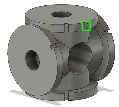
The Cura slicer software allows the user to click any planar surface to lie flat on the build plate. Simply click the highlighted surface, and the winding holder will lie perfectly flat as intended. All of the other surfaces on the holder are curved, so it is difficult to lay the piece flat without this planar surface.
- The print takes around 8-10 hours on my Ender 3 with standard settings.
-
The most difficult supports to remove from the print are the ones that reside within the carbon brush houses as shown in blue below:
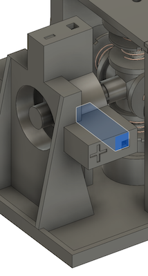
Using a small flat-edge screwdriver, gradually press through the exterior hole and shove the internal supports out the other end. This can be quite challenging, but the supports will eventually come out. The other supports in the print are easier to remove.
- The rotor (shaft) might not fit easily within the bearings at first. File or sand the rotor so that it fits in the bearings snugly. You don’t want it to be loose within the bearings.
Assemble the Windings
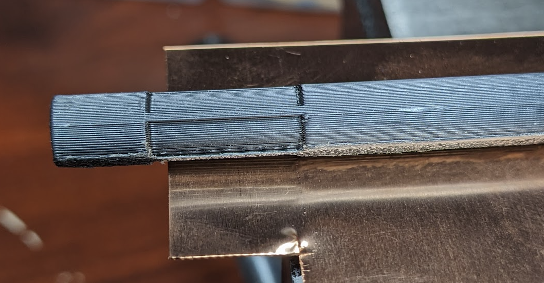
The soft iron winding cores need to leave 10mm exposed after insertion into the holder, as shown below:
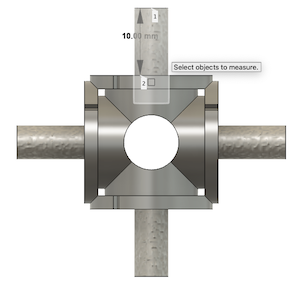
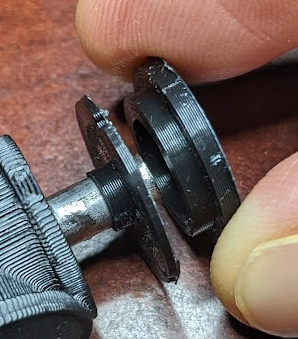
Insert the iron rod fully into the holder, mark off 10mm exposed, and cut to length. It is important to leave no more than 10mm exposed so that the windings clear the stators when rotating. Attach the winding washer to the end of the core leaving 2mm exposed:
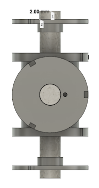
This bit on the end will be clamped in a drill when winding the electromagnetic coils. Repeat for all windings. Depending on the design (see below), there will be either two or four windings. Add a drop of superglue in the core holder to keep each iron core in place. Once these dry, position the winding washers on the ends of their cores. Do not glue them yet, just get them in place as follows:
Note that the collar of each washer is facing the inside and not the outside. This is important. Next, for each washer in turn, place a small drop of superglue on the inside surface as circled in green below:
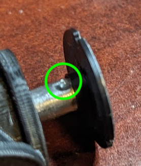
Move the washer inward while rotating it on the core, such that the glue enters between the core and the washer. When done, the washer should leave exactly 2mm of exposed core on the end. To make this easy, print the small spacer part and use it to push the washers inward. The spacer has a collar with depth 2mm.
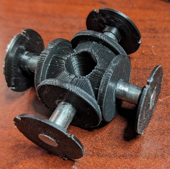
The assembly should look as follows after the washers are placed and glued:
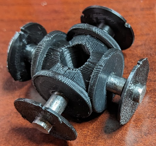
Let everything dry and then assemble the motor to ensure that it will rotate freely:
Wind the Electromagnetic Coils
Each washer has a 1mm hole near the central hole as circled in green below. The purpose of this hole is to provide the magnet wire an exit from the coil and to get the winding started.
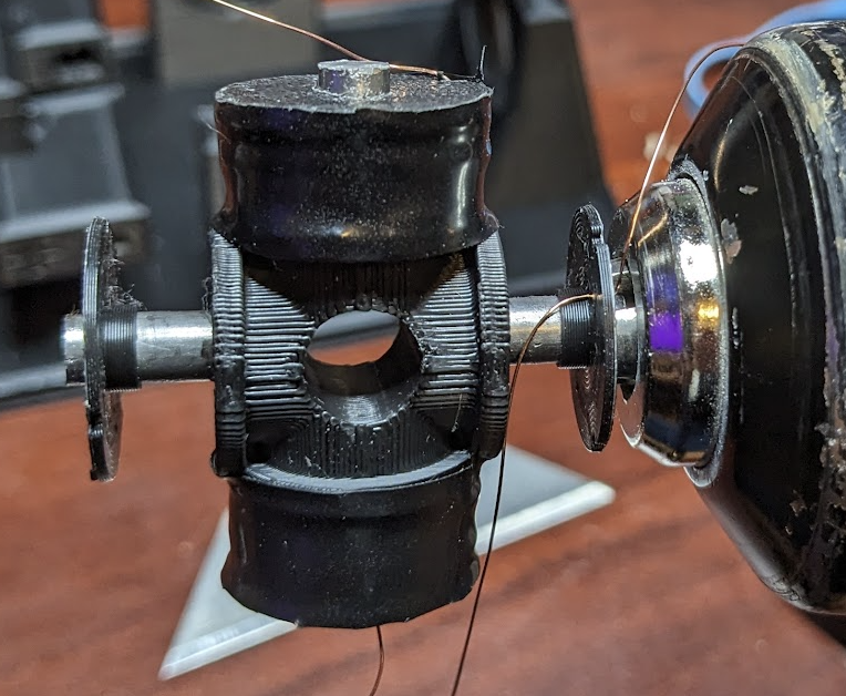
If your 3d printer is sufficiently accurate, then this hole will be present and will accept the 30 AWG enameled magnet wire. If the hole is not preserved, then you might need to open it up with a pin. The coil should look as follows just prior to engaging the drill:
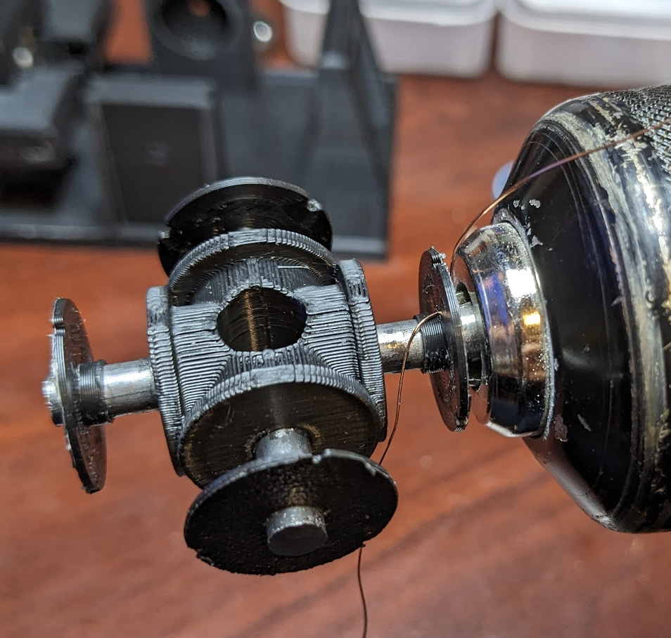
Note that a good length of wire has been pulled through the small hole exiting to the right (the wire spool lies below the drill in the image). A good strategy is to clamp the drill in a vise, guide the feed wire with one hand, and operate the drill with the other hand.
Now for the tricky part, the winding direction. Study up on the “right-hand rule” of electromagnetism. There are many good articles. This one is helpful, particularly the following visual:
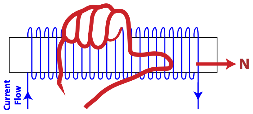
Another view of the right-hand rule is shown below, taken from one of the motor designs:
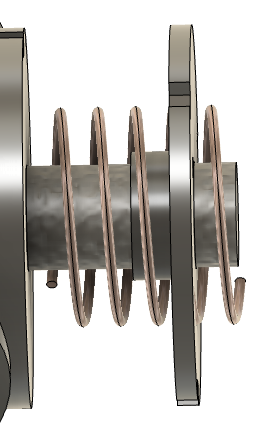
In the above, the outward-facing (right) end of the iron core would have north polarity.
The specific winding direction to use at this point depends on the design you are building. See the three designs below for winding polarities to use for your design.
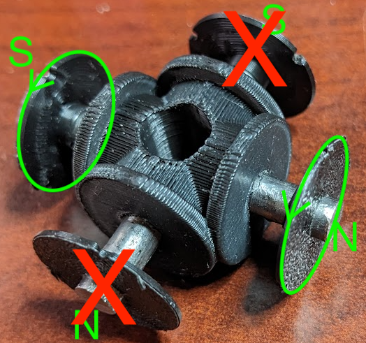
Two-Stator Two-Coil Polarities
The red Xs in the figure below show parts that are not actually present in this design. The green arrows show the directions that the washers should turn when winding each coil. As shown, the washers on either end turn in the same direction. This means that the drill direction will remain the same throughout the entire winding procedure.
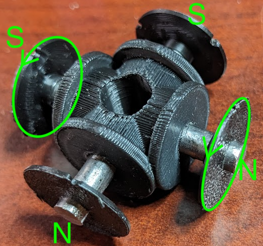
Two-Stator Four-Coil Polarities
This is just like the two-stator two-coil design except that the magnets run along both axes.
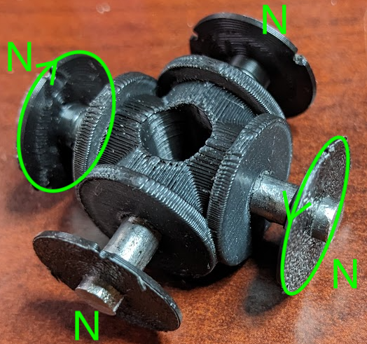
Four-Stator Four-Coil Polarities
The polarities in this design must be such that each end is north. To achieve this, wind one end in the direction indicated in the image below. Once the first coil is wound, reverse the drill and wind the other coil in the opposite direction. Then wind the coils along the other axis in the same way.
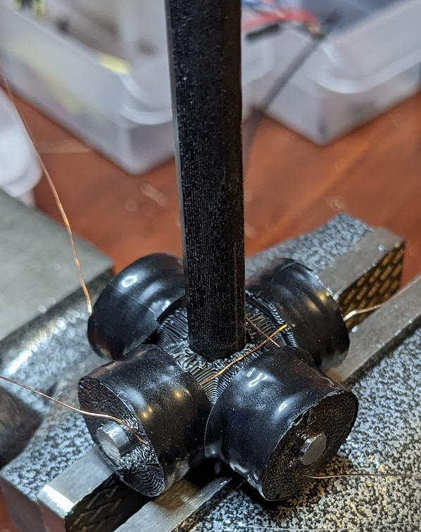
Winding
When you’re ready, slowly start the drill and begin winding the coil. Try to get the layers as even as possible. Fill in the valleys that develop and don’t worry about making them perfect. Stop the drill when the first coil is wound. Guide the feed-end of the wire across the winding holder using the notches as guides and then continue winding the other end in the direction shown according to your design above. Once the other end is complete, secure the wire, leave a good length exposed for later wiring, and then cut the wire:
Wrap the coils in electrical tape. If your design involves coils along the other axis, then repeat the procedure to obtain the required polarities:
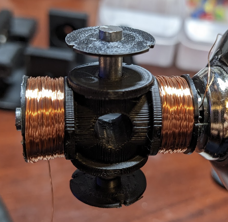
A final four-coil design should look as follows:
Use a multimeter to test all coils for integrity and roughly similar resistance. A few tips at this point:
- The wire is enameled, meaning its coated in a thin layer of clear plastic to prevent shorts within the coil. The enamel must be removed from the wire ends prior to testing or soldering. Simply burn it off with a flame.
- Having built and wound several cores like these, I have found that each axis (two coils) typically has about 15 ohms of resistance. With a 12-volt power supply, this would result in 12.0 / 15.0 = 0.8 amps of current running through the wire, which is acceptable. The final assembly including the commutator and brushes will have more resistance, which will further decrease the current. The final current needs to be within the operating range of the wire. This workbook suggests the fusing current of 30 AWG wire is 10 amps, so the final current running through the coils must be substantially below this.
Build the Commutator
Cut a width of copper sheet that will fit within the recessed sections of the rotor:
Place the section in the bender:
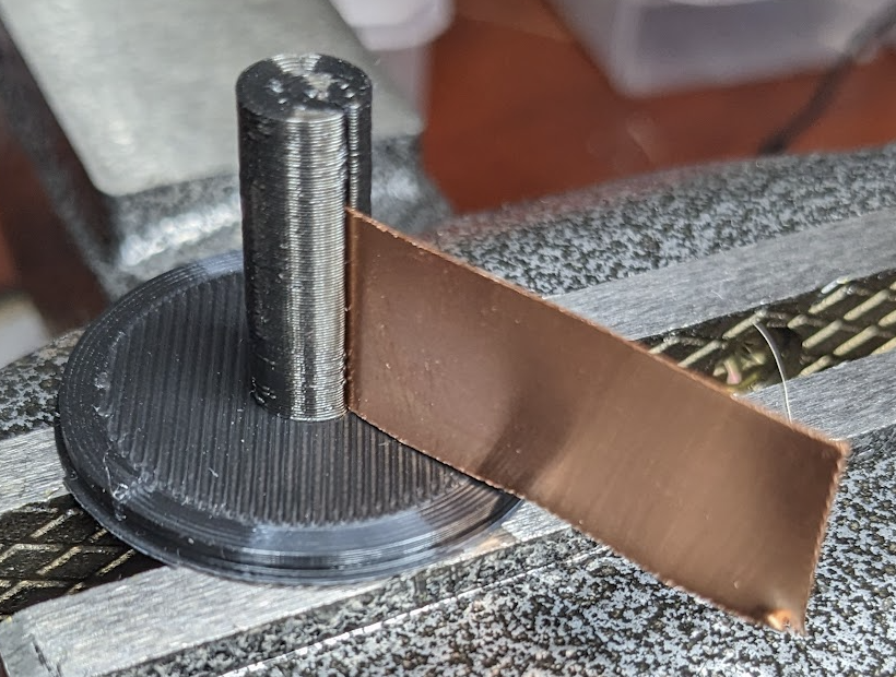
The outside diameter of bender is the same as the recessed sections of the rotor. Thus, wrapping the copper around the bender provides a curvature that will match the recesses of the rotor:
Cut sections of the bent copper that will lie in the recesses:
The commutator segments need to lie entirely within the recesses and not have rough edges that will catch on the brushes. Do not glue the segments to the rotator yet. They still need to be soldered to winding coils, and if you attempt to solder commutator segments while they are glued to the rotor, you will melt the plastic rotor.
Position the winding cores on the rotor and trim the wires to remove excessive wire:
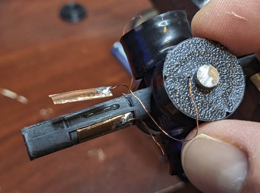
Next, solder the winding coils to the commutator:
A few tips on this step:
- The smooth copper sheet might not adhere well with the solder. File or sand the surface end of the commutator segments that you will solder to the wires.
- If you value your fingers, then use a soldering station as listed at the top of this page.
- Do not allow the solder to go very far up the commutator segment. The brushes need room to run unimpeded across the commutator surfaces.
Next position the winding holder precisely on the rotor and begin gluing them into their recesses:
Very important notes:
- The winding cores must be oriented such that the iron cores are exactly aligned with the gaps between the commutator segments. Think of it this way: When the iron cores are pointing directly at their stator magnets, the electromagnets need to be in a neutral or unpowered position between one polarity and the other.
- The commutator segments need to be placed in the correct sequence of recesses that depends on your design:
- Two-stator two-coil: The two commutator segments may be placed in either of the rotor recesses. The only impact of the order is the direction that the motor will rotate when powered. Motor direction is also controlled on the positive and negative power leads, so the commutator placement really does not matter here.
- Two-stator four-coil: Need a figure here.
- Four-coil four-stator: Need a figure here.
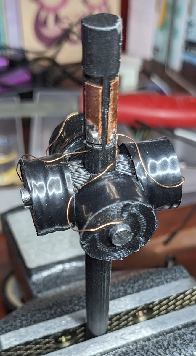
The final assembled commutators should look as follows:
Build the Power Circuit
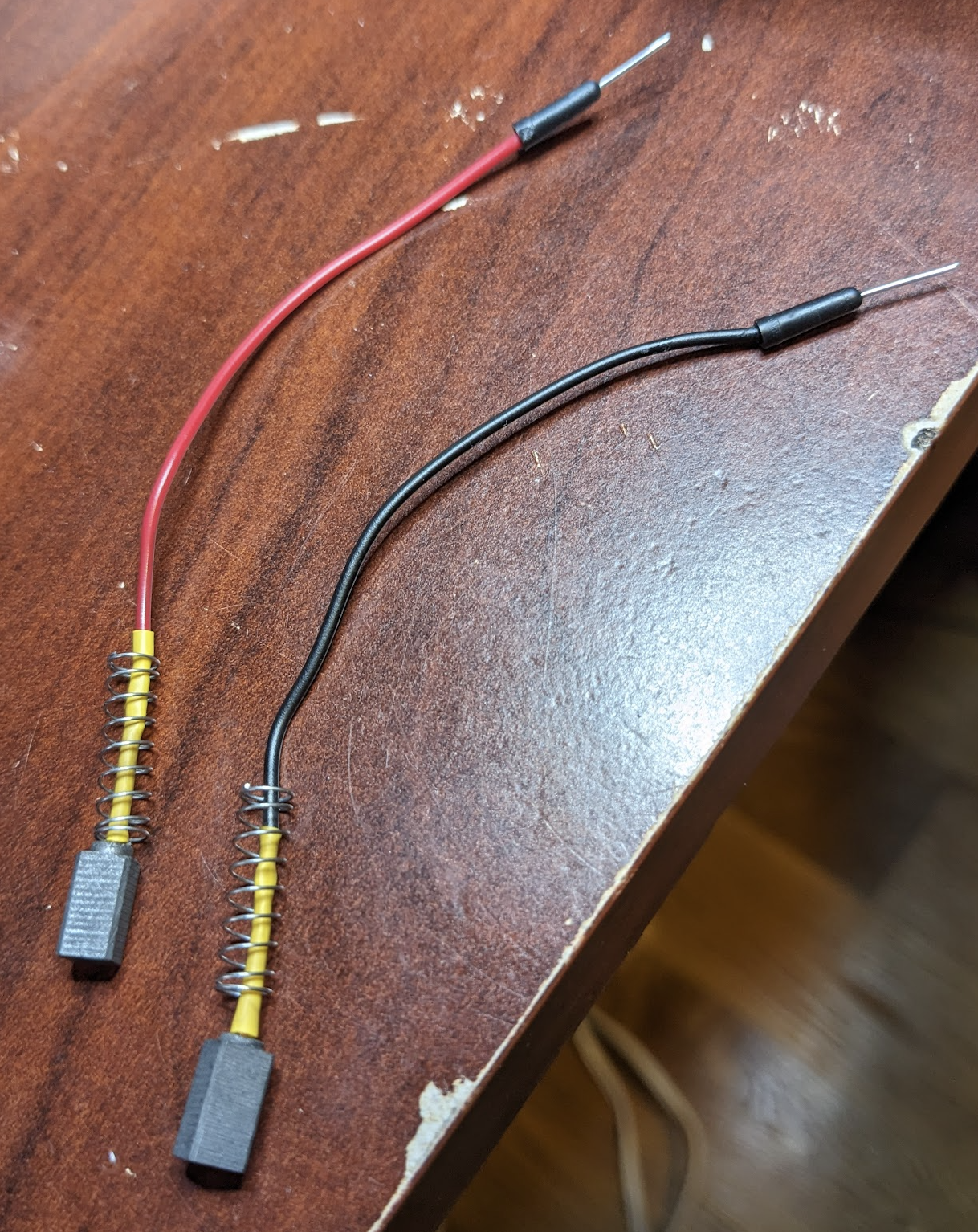
Solder the carbon brushes to jumper wires. You’ll need a number equal to the number of stator magnets in your design:
Insert the brush wires into the motor base. The following image shows the brushes in a two-stator design:
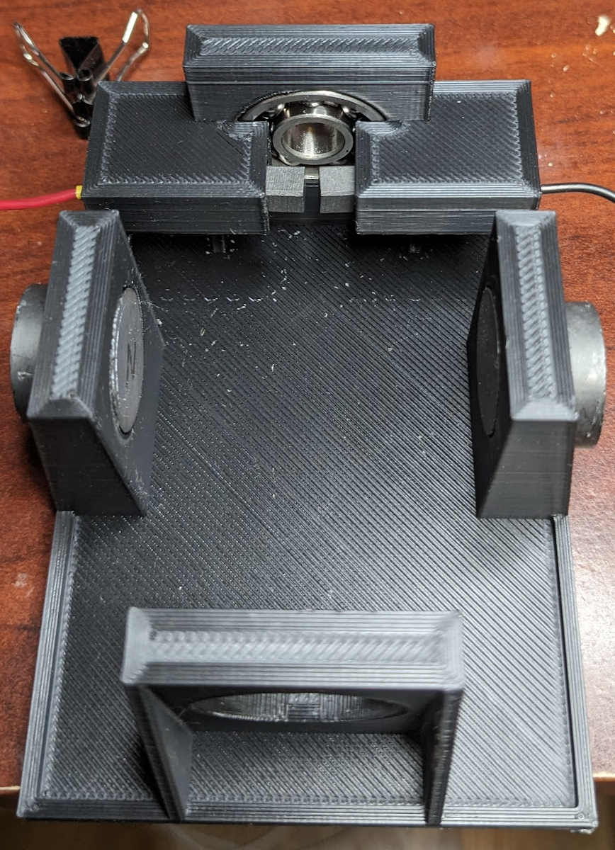
The brushes should move freely when the wires are pulled, with the springs returning them to their extended positions. If the brushes catch when pulled or do not spring back, then remove the brushes and file the insides of the brush housings. You can wire the DC power source directly to the brush wires, or you can patch it together with a breadboard as shown below. The breadboard provides flexibility for building circuitry around the motor (see Other Fun Stuff below):
Install the Stator Magnets
The stator magnets must be arranged such that the internal surfaces – those facing the coils as they rotate – alternate between north and south. In the two-stator designs, one side should be north and the other south. In the four-stator design, the inside-facing stator magnets should alternate north, south, north, and south. Only this relative alternation matters. It does not matter which of the two axes holds the north stators and which holds the south stators. In all of the photos and videos on this page, there are two disc magnets at each stator location.
Assemble the motor to ensure that it will rotate freely:
Test and Fix
With a bit of luck, you can power the motor circuit, give the rotor a twist, and it will run:
Common problems:
- Bad power circuit: You should be able to connect a multimeter to the brush wires that exit the base and measure resistance (ohms) of each coil axis. All axes should be roughly similar (e.g., within 1 ohm) for the 4-coil designs, which have two axes.
- Stuck brushes: The internal surfaces of the brush houses might be rough. If a rough bit catches a brush as the motor rotates, this might prevent the brush from coming back into contact with the commutator, thus breaking the power circuit. If the brushes do not move smoothly in and out of their houses, then remove them, file the insides of the brush houses, and reassemble.
- Power short: If the brushes contact multiple commutators simultaneously, the power might short-circuit. The DC power source linked at the top will automatically cut off on shorts. Revisit the commutator assembly if this happens. The four-coil, four-stator and two-coil, two-stator designs have the highest risk of such a short, since the positive and negative brushes contact adjacent commutator segments. When the commutator is in a neutral power position and begins to transition to the next, a positive and negative brush may both contact the same segment. The DC power supply well self-protect; however, if you have other circuitry built around the motor as shown farther down, a short can damage other components including a connected Raspberry Pi.
- Weak stator magnets: The motor base has recesses for single magnets, which might not be strong enough on their own. Adding magnets to the outside increases the field strength substantially. This also conveniently holds the inner magnets in place without adhesive.
Designs, Videos, and STL Files
The following sections provide CAD viewers, STL file downloads, and advantages and limitations for three alternative motor designs.
Two-Stator Two-Coil (Download)
Advantages:
- Simple assembly: Only two electromagnetic windings. Easiest support removal.
- Lightweight rotor assembly
- Higher rotational speed than the two-stator four-coil design
Limitations:
- Rough rotational dynamics: The electromagnetic windings experience substantial time separated from the stator magnets’ fields. As a result, the motor’s rotational speed tends to fluctuate during each revolution.
- Possibility of shorts: The commutator segments must be carefully built, since the two brushes are nearby the same commutator segment and may short across the segment.
Two-Stator Four-Coil (Download)
Advantages:
- Smooth rotational dynamics: The electromagnetic windings experience less time separated from the stator magnets’ fields. As a result, the motor’s rotation speed is more consistent than the two-stator two-coil design.
- Unlikely shorts: The two brushes are never near the same commutator segment and thus are unlikely to short.
Limitations:
- Heavy rotor assembly
- Slow rotational speed
Four-Stator Four-Coil (Download)
Advantages:
- Highest torque: The rotor assembly is heavy; however, the winding cores are always actively pushing from and pulling toward nearby stator magnets.
- Smooth rotational dynamics
Limitations:
- Complicated assembly: Includes four coils and four brushes.
- Possibility of shorts: The commutator segments must be carefully built, since adjacent brushes are nearby the same commutator segment and may short across the segment.
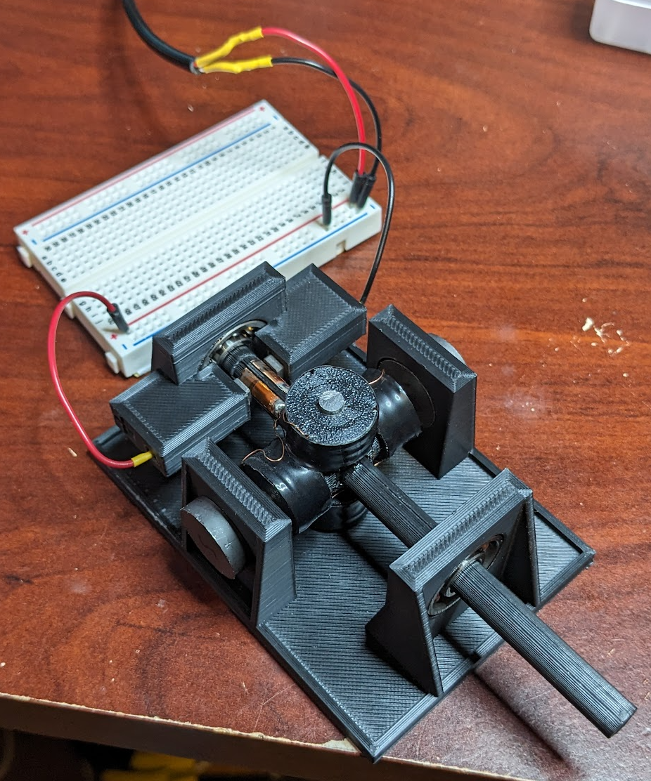
Other Fun Stuff: Web-Browser Control with a Digital Tachometer Circuit
This is similar to the videos above, except that this version integrates the motor with a web-browser on/off control accessible from any device on the network (e.g., a smartphone):
The web-browser control is implemented using my raspberry-py package for REST-based control of circuits running on a Raspberry Pi. The web-browser toggle calls a REST endpoint running on the Pi, which switches the orange relay in the middle of the breadboard seen in the video. This switch is also indicated by illumination of the red LED. I’ve also added a digital tachometer circuit to estimate rotational speed. The speed is displayed in the browser as revolutions per second (RPS). This motor – the 4-coil 4-stator design – runs at about 30 RPS (1,800 RPM). The circuit is shown below:
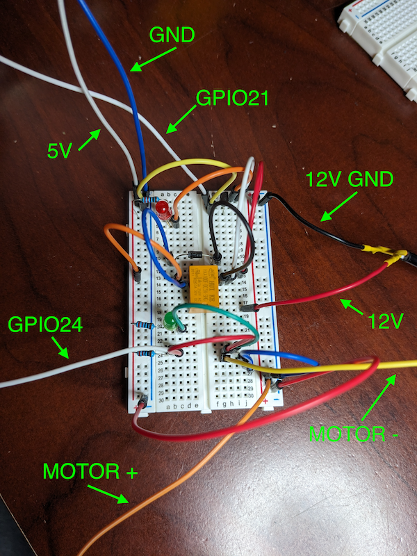
As noted above in the Test and Fix section, building circuitry around the motor and its high-voltage power supply can be hazardous to your electrical components. A short circuit can easily damage your Raspberry Pi. I did exactly this when attempting to run the two-coil two-stator design on the circuit shown above. The power shorted across a commutator segment, blew up a transistor, and damaged a GPIO port on the Raspberry Pi. Builder beware!
Things to Improve
- Winding washers do not always stay put.
- The risk of shorts across commutator segments is increased when the segments are not sufficiently recessed.
References
- Voltage, Current, and Resistance (a basic overview)
- Electromagnets: In particular, the author’s coildata.xls spreadsheet is a fantastic way to learn about the ingredients of an electromagnet (coil gauge, winding count, current input, gauss output, etc.)
- Brushed DC electric motor (Wikipedia).
Other parts can be found here.